Kenneth W Decker
age ~72
from Farmersville, TX
- Also known as:
-
- Kenneth Wayne Decker
- Kenny W Decker
Kenneth Decker Phones & Addresses
- Farmersville, TX
- 330 Bonnie View Dr, Princeton, TX 75407 • (469)4502043
- Greenville, TX
- 12627 Fm 2756, Farmersville, TX 75442
Work
-
Position:Building and Grounds Cleaning and Maintenance Occupations
Education
-
Degree:Bachelor's degree or higher
Emails
Us Patents
-
System For Evaluating The Flow Performance Characteristics Of A Device
view source -
US Patent:51074419, Apr 21, 1992
-
Filed:Oct 31, 1990
-
Appl. No.:7/606872
-
Inventors:Kenneth L. Decker - Garland TX
-
Assignee:Otis Engineering Corporation - Dallas TX
-
International Classification:G01F 2500
-
US Classification:364510
-
Abstract:A system for determining the flow performance of a valve by first measuring certain flow parameters of the valve with the stem fixed in a plurality of different positions between full open and full closed and then calculating a value of flow coefficient for each. The flow parameters of the valve are then measured with the stem dynamically moving under a plurality of different flow conditions. Mathematical relationships are derived in accordance with certain procedures for calculating the flow rate of the valve under each of the different flow conditions.
-
Fluid Flow Regulator
view source -
US Patent:48586447, Aug 22, 1989
-
Filed:May 31, 1988
-
Appl. No.:7/200138
-
Inventors:Kenneth L. Decker - Garland TX
-
Assignee:Otis Engineering Corporation - Dallas TX
-
International Classification:F16K 1514
-
US Classification:137504
-
Abstract:A fluid flow regulator in which the fluid flow therethrough is restricted twice, first through a fixed orifice in a slidable piston and then through a variable flow restrictor which is a spring. This spring is axially aligned with and bears against the piston, and fluids issuing from the orifice empties into the interior of the spring, the end of the spring opposite the piston being closed. Fluids thus flow from within the spring through the gaps between its coils and into a chamber surrounding the spring, and from there exits through the outlet of the regulator. The gaps between the spring coils are quite narrow and cause the flow of fluids to be restricted this second time. This restriction is variable since the piston moves as the differential pressure thereacross varies which causes the length of the spring to vary accordingly. This in turn varies the size of the gaps. In this manner, the regulator compensates automatically to provide a fluid flow rate which is substantially constant.
-
Coiled Tubing Deployed Inflatable Stimulation Tool
view source -
US Patent:58329986, Nov 10, 1998
-
Filed:May 3, 1995
-
Appl. No.:8/433787
-
Inventors:Kenneth L. Decker - Carrollton TX
John H. Yonker - Carrollton TX
Wallace G. Wilke - New Iberia LA
Jeffrey S. Walter - Duncan OK
James C. Tucker - Duncan OK
Kenneth W. McIntyre - Duncan OK
Michael L. Connell - Duncan OK
Kenneth D. Caskey - Duncan OK -
Assignee:Halliburton Company - Dallas TX
-
International Classification:E21B 33127
-
US Classification:166185
-
Abstract:A resettable well stimulation tool is lowerable into a well bore on a length of tubing through which pressurized fluid may be forced into the tool to inflate a packer portion carried by the tool and then discharge a stimulation fluid into a portion of the well bore sealed off by the packer portion. During the inflation cycle of the tool pressurized fluid is forced downwardly into an annular tool body inflation chamber that communicates with an inflatable packer carried by the tool body. A perforated tube member coaxially carried in the inflation chamber serves to vertically distribute the inflation pressure along the length of the packer and assure its even inflation. In a straddle packer embodiment of the tool inflation and stimulation passages extend internally through the tool and are sealingly separated by an internal crossover structure, with the inflation passage being in communication with upper and lower packer members. The internal inflation passage eliminates the previous necessity of communicating the upper and lower packers with inflation tubing externally coiled around the tool body. A longitudinally intermediate portion of the tool body has a telescoping expansion joint portion to compensate for the longitudinal forces exerted on the body by inflation of the packers.
-
Coiled Tubing Deployed Inflatable Stimulation Tool
view source -
US Patent:52714616, Dec 21, 1993
-
Filed:May 13, 1992
-
Appl. No.:7/882308
-
Inventors:Kenneth L. Decker - Carrollton TX
John H. Yonker - Carrollton TX -
Assignee:Halliburton Company - Duncan OK
-
International Classification:E21B 33127
-
US Classification:166185
-
Abstract:An inflatable stimulation tool designed to be deployed by coil tubing having a shuttle valve which reciprocates within the bore of a tubular mandrel. The shuttle valve, in cooperation with a reciprocally movable outer mandrel which is disposed about an inner mandrel, opens and closes various ports in the device to alternately seal and unseal the inflatable packer element. The shuttle valve also operates to open and close a flow passage through the inner mandrel to permit the passage of various stimulation fluids through the tool and into the well bore. Upon deflation of the inflatable packing means, which leaves the packing means in a somewhat distended state, the element is urged to its original close relationship with the mandrel by a return spring which cooperates with the lower tool structure to which one end of the rubber packing element is clamped to longitudinally stretch the element.
-
Gas Lift Valve
view source -
US Patent:50661981, Nov 19, 1991
-
Filed:Jun 4, 1990
-
Appl. No.:7/533019
-
Inventors:Kenneth L. Decker - Garland TX
-
Assignee:Otis Engineering Corporation - Dallas TX
-
International Classification:F04F 118
-
US Classification:417 54
-
Abstract:A gas lift valve of the unloading type having a main valve for controlling fluid flow between a well casing and a well tubing, a volume of compressible liquid a spaced distance from said main valve and subject to casing pressure, and a pilot valve between the main valve and the compressible liquid for controlling opening and closing of the main valve by permitting casing pressure to act thereon or to isolate it therefrom as the volume of the compressible liquid changes in response to changes in casing pressure to which it is subjected. Gas lift well systems utilizing such gas lift valves and methods for operating such gas lift well systems are also disclosed.
Resumes

Kenneth Decker
view sourceLocation:
United States

Kenneth Decker
view source
Kenneth Decker
view source
Kenneth Decker
view source
Kenneth Decker
view sourceLocation:
United States

Kenneth Decker
view sourceLocation:
United States
Name / Title
Company / Classification
Phones & Addresses
Co-Owner
Composite Effects, LLC.
Theatrical Equipment & Supplies
Theatrical Equipment & Supplies
6786 Pecue Lane, Suite I, Baton Rouge, LA 70817
(225)7567875
(225)7567875
DECKAIR FLYING SERVICE, LLC
POUR & PLAY SURFACING, LLC
Myspace
Flickr

Kenneth Decker
view source
Kenneth Decker
view source
Kenneth Decker
view source
Kenneth Decker
view source
Kenneth Decker Prieto
view source
Kenneth Ray Decker
view source
Kenneth Decker
view source
Kenneth B Decker
view sourcePlaxo

Kenneth Decker
view sourceanuoluwa farm
Classmates

Kenneth Decker
view sourceSchools:
Belleville Elementary School 3 Belleville NJ 1941-1950
Community:
Susan Harrington, Joyce Angileri, Robert Migliara, Brenda Bergamotto

Kenneth Decker
view sourceSchools:
Greenbelt Junior High School Greenbelt MD 1973-1976
Community:
Betty Fleming, James Vaughan

Kenneth Decker
view sourceSchools:
Mount Olive High School Budd Lake NJ 1986-1990
Community:
Donna Dickson

Kenneth Decker
view sourceSchools:
North Rose-Wolcott High School Wolcott NY 1968-1972
Community:
Bonney Milan, Donald Dalton, Caude Hine, Patti Caster

Kenneth Decker
view sourceSchools:
Luther Burbank Middle School Los Angeles CA 1950-1954
Community:
Jim Curry, Richard Mendez, Sharon Alvis, Dorine Lunceford, Paul Duran

Kenneth Decker
view sourceSchools:
Orosi High School Orosi CA 1950-1954
Community:
Benny Esparza, Deena Morris, Johnny Burgos

Kenneth Decker
view sourceSchools:
St. Francis of Assisi School Philadelphia PA 1945-1953, Delaware Valley High School Philadelphia PA 1953-1957
Community:
William Mangum, Mike Glickstein, John Kuczynski

Kenneth Decker
view sourceSchools:
East Elementary School Grandville MI 1962-1967, West Elementary School Grandville MI 1967-1970, Grandville Junior High School Grandville MI 1970-1972
Googleplus

Kenneth Decker
About:
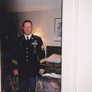
45 YEARS OLD, SPENT 22 YEARS IN THE ARMY, NOW RETIRED AS OF JUNE 2009.
Tagline:
"OLD SARGE"
Bragging Rights:
HAVE 2 OUTSTANDING BOYS, AGES 6 AND 8

Kenneth Decker

Kenneth Decker
Relationship:
Married
Youtube
Get Report for Kenneth W Decker from Farmersville, TX, age ~72


